Republished with permission from the January 2016 issue of Fourteener Motoring Magazine.
When it came time to rebuild the engine for our 1972 Project 914, John Forbes of Black Forest Racing offered to take on the task, and allow us to document the process for this How-To article. We couldn’t pass up the opportunity to learn from an expert. This engine is a 1976 2.0 liter. These steps, however, should be the same for any original 914 4-cylinder engine.
Time Required: 2 to 3 hours, assuming all cleaning has previously been completed and you don’t run into any problems.
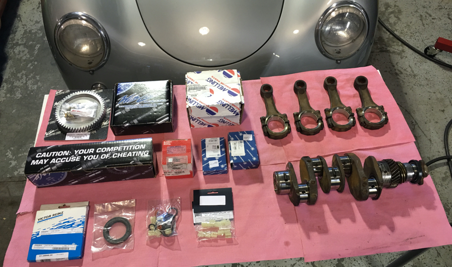
Suggested Materials:
• ProLong Super Lubricant
• Loctite
• 3M Yellow Super Weatherstrip and Gasket Adhesive
• Permatext Aviation Form-a-gasket Sealant Liquid
• Dow Corning 730 FS Solvent Resis tant Sealant
• Haynes Repair Manual for the 914
Optional: Porsche engine expert guiding you through the process.
Cleaning the case:
After disassembly, clean the case in an ultrasonic parts cleaner. Then rinse the case off with water. Then clean it again. Hand clean all of the surfaces. When you think it is fully clean and ready for assembly, clean it again.
Assembling the crank:
Install main bearing on the front of crank. Use ProLong Super Lubricant to keep it lubed until the engine is installed. Note that the bearing must be put on with the dowel pin hole toward the back of the crank.
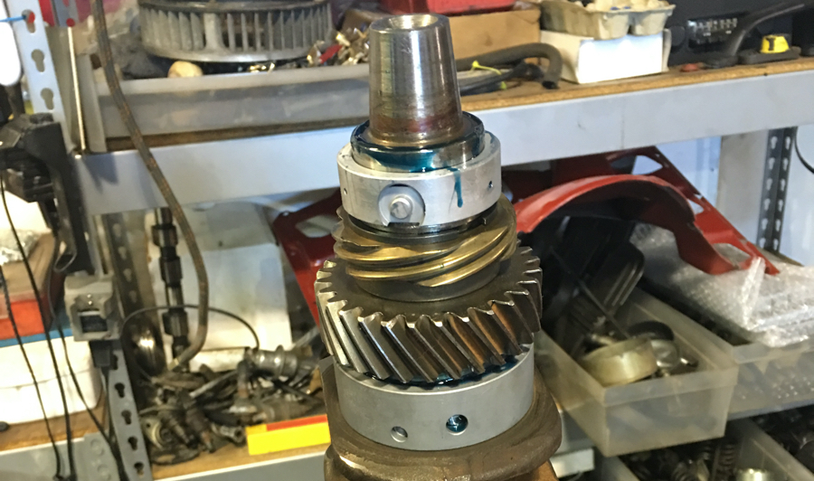
Next, install the crank gear (cam gear). Heat the gear on a hot plate for about 5 minutes, since it can be nearly impossible to get on the crank otherwise. Use gloves to then put the gear on the crank.
After the crank gear, install the spacer. It just slides on and should not require any heat. Finally, install the brass distributer gear. Again this gear should require a little heat to slide on, but not as much as the main gear.
Now the c-clip should be put on. This clip is important, as it keeps everything in its place. Make certain it is seated correctly.
Next, the small crank bearing should be put on, again using ProLong Super Lubricant. Make sure that the bearing is installed with the dowel pin hole toward the back of the crank.
Now install the o-ring, which just sits on the end. The last piece is the seal and fan flange. After putting lube on the inside of the seal, slide it over the flange, then install the flange on the end of the crank. Note that the seal must be installed so that the inner slot is facing the back of the crank.
To keep everything together, torque the crank end bolt tight. Lastly, install the main bearing on the back of the crank, again using a healthy coating of ProLong.
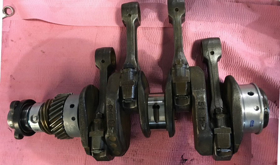
Assembling the rods:
Once the crank is assembled you can install the rods. Preferably, put the rods back on the same lobes that they came off of when you disassembled the engine. Alternatively, you can check the balance/weight of the rods, and install them with the heaviest rod closest to the flywheel, the next heaviest rod next, and so on. Again, use ProLong lube. Make sure that each rod and rod end cap is installed correctly by aligning the numbers on the rod and end cap on the same side.
Tighten the rod nuts lightly to hold them in place. Once they are seated, you can loosen them one by one and use loctite on each. Finally, torque the rod bolt nuts to 28 foot-pounds.
Setting up the case:
When you set the case on the engine stand, for 2.0 liter engines make sure that you put the half that does not have the engine number on it on the stand. With 1.7 and 1.8 liter engines, put the half that has the engine number on it on the stand. This is necessary to install the crank dowel pins.
After the case half is on the engine stand, wipe everything down and make sure there isn’t any dirt or debris on the case surfaces. Also check the case edges for any high spots. Although it is controversial, many engine builders use a file to gently file away any high spots that may be present on the case edges. If you choose to do this, be very careful to let the file do the work, and to only file the spots that are a little high due to a previous owner prying the case apart.
Setting the crank:
Install the four dowel pins in the case where the bearings will be installed. Make sure that the dowel pins aren’t mushroomed on top which could prevent them from properly seating in the bearing. They just slide in.
Now install the center main bearing half in the case. Make sure that the bearing is properly seated over the dowel pin, and that the edges of the bearing are flush with the case. Use ProLong lube on the bearing surface.
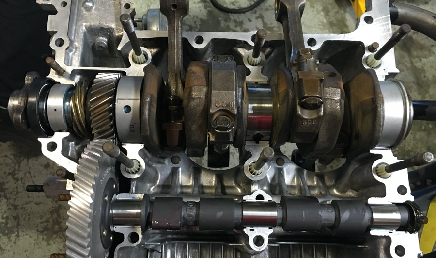
Now you are ready to set the crank. Make sure the dowel pin holes are aligned with the dowel pins. You can set the crank down in the case, and gently turn each bearings until it clicks into place. This might take a little practice, but, it is worth the effort. This is likely the most tedious aspect of the build. If not installed correctly, the case will not seat properly, and the engine won’t turn over.
After setting the crank, install the flywheel spacers. The rear main seal should then be installed on the crank. It is better to install the rear main seal now, then after the case is assembled, because you can avoid hammering it in and possibly damaging the seal. Since the spacers won’t fit through the rear main seal, install them before inserting the seal. We will check the crank endplay later.
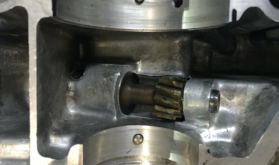
Once the crank is in place, install the distributer drive. Make sure that you use the correct oiling spacer on the end of the distributer drive. The spacer looks like a small washer and has three grooves on each side. The groves allow oil to enter in this area. Although you can install the oiling spacer with either side up, it is important to use the correct spacer. Put the oiling spacer on the end of the distributer drive and slide it into the case, all the way down to engage with the distributer gear on the crank.
Next, install the distributer. Once the distributer is slid in, time the distributer to the crank. Do this by aligning the rotor with the notch on the side of the distributer, simultaneously while the crank is set with the number one rod at top dead center. Once this is aligned, tighten the distributor hold down to keep it in place.
Setting the cam:
We used a new cam from Web Cams, cut to stock factory specs, and a new cam gear. The cam gear should be installed with the bolts that came with it, assuming there is enough clearance for the oil pump (See the Cam Gear Bolt Tip on page 48). Align the cam gear on the cam so that the dot on the cam gear is at 9 o-clock, while the number 1 cam lobe is pointing straight up, and the number 4 cam lobe is pointed toward three o’clock. Once the cam gear is properly aligned on the cam, tighten the bolts to seat the gear, and then loosen the bolts one by one to put loctite on them. Torque the bolts to 18 foot-pounds.
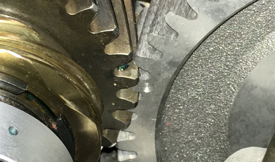
Once the cam is ready, install the cam bearings in the case, and lube them with ProLong. Finally, install the cam plug. Make sure it is clean and use Permatext Aviation Form-a-Gasket Sealant Liquid around the cam plug to keep it sealed. Use the cam lobe lubricant that came with the cam on each lobe, and place the cam into the case. When you install the cam, time it with the main gear on the crank by aligning the dot on the cam gear between the two dots on the main crank gear, as seen in the picture below.
Assembling the case:
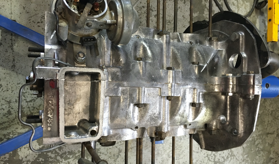
The next step is to prepare the case halves for assembly. Start by putting the case bolts into the case half that is in the engine stand. Install each case bolt with new vibration dampers.
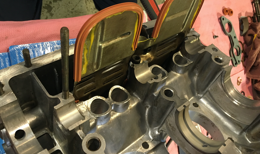
Next, install the windage tray oil baffle seals on the windage tray. You can use 3M Yellow Super Weatherstrip and Gasket Adhesive to hold them in place. Also make sure to replace the o-ring seal on the end of the windage tray tube. When installing the windage tray line up the loop hole at the base of the tray with the hole in the case half for the case bolt, which holds the windage tray in place. When you assemble the case halves, make sure to put this bolt in before tightening the case bolts because it can be difficult to get it in otherwise.
To seal the case, John uses Dow Corning 730 FS Solvent Resistant Sealant. It isn’t cheap, at $90 a tube. The sealant is installed only on one case half. Although you want to cover all of the surfaces that match up with the other case half, including the inner surfaces around the case bolt holes, do not use too much sealant.
Install the other half of the main bearing in the case half not on the engine stand, again using the dowel pin and ProLong lube, and your ready to put the case halves together. While putting the two case halves back together make sure that the rods are properly aligned with the cylinders.
John uses Permatext Aviation Form-a-Gasket Sealant Liquid around the case bolts to seal them. Torque the large case bolts first, working diagonally (as specified in a Haynes manual). Large case bolts are torqued to 25 foot-pounds. Then tighten and torque the small case bolts, which should be torqued to 18 foot-pounds. Double, no triple, check that you have all case bolts tightened, as there are quite a few in hard-to-find places.
Once all of the case bolts are torqued, you are done. You can turn the crank, but, no more than 1/8 of a turn. If it turns freely, but tight, it is an indication that everything is assembled correctly. Do not turn the crank more than 1/8 of a turn. Without the flywheel in place the crank can shift from end-to-end, causing the distributor gear to become disengaged from the distributor drive.


About The Author: Steve
More posts by Steve